When you design a battery-powered Christmas string, the instinct is to save power by dimming the LEDs. Break the string current apart, though, and you get a counter-intuitive result: under an animated pattern, roughly two thirds of the current is not consumed by the lit nodes at all. It is drawn continuously by the nodes that happen to be off, as standby current. This report takes the energy budget apart and turns runtime from a feeling into a formula you can check.
- 1. Where the current goes: two thirds to nodes that are off
- 2. Standby current is a function of voltage — a steep one
- 3. Four design choices that actually move runtime
- 4. The energy account: runtime for a 100-node string
- 5. Three boundaries worth being honest about
- 6. Four recommendations for the product side
- FAQ
When you design a battery-powered Christmas string, the instinct is to save power by dimming the LEDs.
Break the string current apart, though, and you get a counter-intuitive result: under an animated pattern, roughly two thirds of the current is not consumed by the lit nodes at all. It is drawn continuously by the nodes that happen to be off, as standby current.
This report takes the energy budget apart — where the current actually goes, which design choices genuinely save power, and how one formula turns runtime from a feeling into a number you can verify. The figures come from measurements and interpolations on a wide-range constant-current addressable driver IC (P9165A) in a single-cell direct-drive topology.
1. Where the current goes: two thirds to nodes that are off
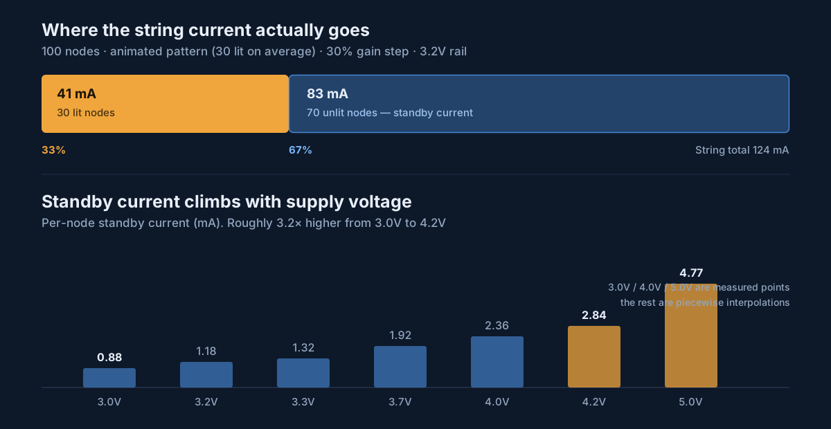
Take a concrete case: a 100-node string running a chase animation, with 30 nodes lit on average, gain set to the 30% step, powered from a 3.2V rail.
| Current component | Current (mA) | Share |
|---|---|---|
| 30 lit nodes | 41 | 33% |
| 70 unlit nodes (standby) | 83 | 67% |
| String total | 124 | 100% |
There is an important corollary here: the more animated the pattern, and the smaller the fraction lit at any instant, the larger the standby share becomes. A product whose selling point is “individually addressable, fine-grained chase animation” is precisely the product where standby dominates — the prettier the animation, the more the power lever concentrates on standby.
So the selection priority for battery applications inverts the mains-powered one: per-node standby current matters more than per-node operating current. Under the same conditions, common addressable string ICs draw up to 369mA for the whole string — about 3x the 124mA above — and that gap comes mainly from standby: 0.88mA versus 2.89mA at 3.0V.
2. Standby current is a function of voltage — a steep one
The second easily missed fact: standby current is not a constant. It climbs quickly with supply voltage.
| Supply voltage | Per-node standby current | Relative to 3.0V |
|---|---|---|
| 3.0V | 0.88 mA | 1.00x |
| 3.2V | 1.18 mA (interpolated) | 1.34x |
| 3.3V | 1.32 mA (interpolated) | 1.50x |
| 3.7V | 1.92 mA (interpolated) | 2.18x |
| 4.0V | 2.36 mA | 2.68x |
| 4.2V | 2.84 mA (interpolated) | 3.23x |
| 5.0V | 4.77 mA | 5.42x |
This curve rewrites the battery-selection logic. LiFePO4 beats Li-ion for reasons beyond cold-weather performance — its 3.2V discharge plateau sits entirely in the lowest standby-current region, while Li-ion sweeps from 4.2V down to 3.0V and spends its first half at nearly three times the standby draw of its last. Averaged across a full discharge, the LiFePO4 platform saves more than 30% of standby energy.
Put differently, on a battery string choosing a lower platform voltage is itself an energy-saving design decision, not just a safety or cost one.
3. Four design choices that actually move runtime
Wide-range constant current: no boost stage, and no “dim by night three”
A 3V5V operating window overlaps almost exactly with the full discharge range of common batteries: a single Li-ion cell 4.2V→3.0V, LiFePO4 3.6V→2.8V, 3xAA alkaline 4.5V→3.0V — all three fall inside the window. That means the string can hang directly off the battery, with no boost or regulation stage, saving 1015% conversion loss outright along with the associated BOM, PCB area, and potting complexity.
The constant-current output also fixes an experience problem. Resistor-limited strings on the market dim linearly as battery voltage falls, which is why “bright on night one, visibly dim by night three” is such a common complaint. A constant-current output keeps bead brightness flat across the entire 4.2V→3.0V discharge, going dark only when the charge is genuinely gone — a difference you can plot as two curves on one chart.
Eight gain steps: a programmable runtime dial
Eight gain steps let firmware adapt brightness to remaining charge: step down automatically when the battery hits a threshold, turning “suddenly goes dark” into “drops into low-power mode and runs N more hours”. The same hardware can also expose a user-selectable “party mode / long-runtime mode” pair with no BOM change.
| Gain step | Per-node operating current @3.3V | Relative to 100% |
|---|---|---|
| 100% | 6.53 mA | 1.00x |
| 89% | 5.72 mA (interpolated) | 0.88x |
| 79% | 4.98 mA (interpolated) | 0.76x |
| 68% | 4.18 mA (interpolated) | 0.64x |
| 60% | 3.59 mA (interpolated) | 0.55x |
| 47% | 2.63 mA (interpolated) | 0.40x |
| 38% | 1.97 mA (interpolated) | 0.30x |
| 30% | 1.38 mA | 0.21x |
Time-multiplexed R·G·B·W: peak current cut to about a quarter
Batteries — especially alkaline cells and small lithium packs whose internal resistance rises in the cold — are most vulnerable to the instantaneous voltage sag caused by peak current. Driving the four channels in time slices removes roughly 3/4 of the peak, directly reducing brown-out resets and the “dims or flickers in the cold” failure mode. This never shows up in the average power budget, but it decides whether a battery product works reliably outdoors in winter.
Two-wire carrier: thinner wire, fewer joints
Dropping a conductor is worth more than BOM on a battery product. The wire runs thinner and softer, which improves outdoor wrapping; solder joints fall by about a third, cutting failure rate; and there is less wiring surface to seal when potting — a real simplification for the battery box, already one of the biggest sources of field complaints.
4. The energy account: runtime for a 100-node string
Feeding those parameters in gives a table you can set product specs from. Power is calculated on a LiFePO4 3.2V platform.
| Condition | String current | 3xAA 2000mAh | 18650 3000mAh | Built-in LiFePO4 6000mAh |
|---|---|---|---|---|
| Static all-on @100% step | 653 mA | 3 h | 5 h | 9 h |
| Static all-on @30% step | 138 mA | 14 h | 22 h | 43 h |
| Animated, 30% lit @60% step | 190 mA | 11 h | 16 h | 32 h |
| Animated, 30% lit @30% step | 124 mA | 16 h | 24 h | 48 h |
To convert to other configurations you only need two expressions:
- String current: Itotal = Nlit × Igain + Noff × Istandby(V)
- Runtime: runtime = battery capacity × DoD ÷ Itotal
Look up Igain in the gain table and Istandby in the voltage table. That second term — the nodes that are off — is the one most estimates omit, and the main source of error.
5. Three boundaries worth being honest about
Runtime claims have to match this table. At 100 nodes the best case (6000mAh + 30% gain + animated pattern) is 48 hours, roughly 6 hours a night for 8 nights. “Six hours a night all season” (180 hours) is not achievable at this configuration. The deliverable claim is “one charge, six hours a night through Christmas week”, or move to a 50-node SKU before quoting hours. Settle this before locking listing copy, or you are pre-building a trust deficit.
State the estimation conditions. The table excludes controller quiescent draw and wiring voltage drop, so real string current runs slightly higher; runtime divides nominal capacity directly with no high-rate derating, which makes the 3xAA column optimistic. Replace interpolated values with measurements before production.
Two parameters need written confirmation from the IC vendor. First, is there a sleep or shutdown mode? A hundred nodes draw 88~118mA on standby alone, so without sleep the controller must physically cut VCC on a timer-off — a design decision that has to be written down. Second, is PWM latched? If frame data is held by the IC after it is written, the MCU can sleep entirely on a static scene rather than refreshing continuously as shift-register architectures require, saving another block of power on the MCU side.
6. Four recommendations for the product side
- Publish both operating and standby current on the datasheet, with the measurement voltage stated. A datasheet giving only operating current cannot be used to estimate runtime in a battery application.
- Treat battery platform voltage as an energy parameter. LiFePO4’s 3.2V plateau sits in the lowest standby region, and that gain scales linearly with node count.
- Use gain steps for charge-adaptive dimming, turning end-of-charge from “suddenly dark” into “steps down and lasts longer”, and expose a user-selectable runtime mode.
- Base runtime claims on measurements, and state the operating condition in the copy (node count, pattern, gain step, pack capacity). The same string varies more than 15x across conditions, so an unqualified number means nothing.
Further reading: safety and mechanical design for battery products in Battery-Powered Light Safety; consistency engineering behind constant-current drive in Constant-Current Drive and Efficiency; the product case for two-wire in The Two-Wire Advantage for Retail Products. Full model parameters are in the product centre.
All figures use a single-string 100-node topology with single-cell direct drive, each IC connected directly across the battery. This differs from 24V multi-segment series measurement conditions and the two cannot be cited interchangeably. Values marked “interpolated” are piecewise interpolations rather than measurements; production designs should rely on measured data from final samples.
FAQ
For a battery-powered addressable string, which parameter matters most?
Standby current, not operating current. Take 100 nodes running an animated pattern with 30 lit on average: the 30 lit nodes draw about 41mA, while the 70 unlit nodes draw about 83mA as standby current — 67% of the 124mA string total. The more animated the pattern and the smaller the fraction lit at any instant, the larger the standby share becomes. So in battery selection, per-node standby current is usually a more useful number than per-node operating current.
Why is LiFePO4 more efficient than Li-ion for battery strings?
Beyond low-temperature behaviour, the key point is that standby current rises sharply with supply voltage — per-node standby goes from 0.88mA at 3.0V to about 2.84mA at 4.2V, roughly 3.2x. The LiFePO4 3.2V discharge plateau sits entirely in the lowest standby-current region, whereas Li-ion sweeps from 4.2V down to 3.0V and spends its first half at much higher standby draw. Averaged over a full discharge, the LiFePO4 platform saves more than 30% of standby energy.
What does constant-current drive buy a battery string?
Two things. First, constant brightness for the whole discharge: resistor-limited strings dim linearly as the battery voltage falls, which produces the classic 'bright on night one, visibly dim by night three' complaint. A constant-current output holds bead brightness flat all the way from 4.2V down to 3.0V, and only goes dark when the charge is genuinely exhausted. Second, no boost stage: a 3V~5V operating window overlaps the discharge range of a single lithium cell or 3xAA, so the string can hang directly off the battery — saving the 10~15% conversion loss of a boost converter along with its BOM and PCB area.
How long does a 100-node battery string actually run?
It depends heavily on the operating condition. With a built-in 6000mAh LiFePO4 pack, an animated pattern (30% lit) and the 30% gain step, the string draws about 124mA and runs about 48 hours. The same pack driving a static all-on scene at the 100% step (653mA) lasts about 9 hours. Note that 48 hours is roughly 6 hours a night for 8 nights — short of 'every night through the season', so runtime claims should be framed as something deliverable, such as 'one charge, six hours a night through Christmas week', or moved to a lower node-count SKU.
How do I estimate runtime myself?
Two formulas. String current I_total = N_lit x I_gain + N_off x I_standby(V); runtime = battery capacity x DoD / I_total. Look up I_gain in the gain table and I_standby against your battery platform voltage. Note this estimate excludes controller quiescent draw and wiring voltage drop, so real current runs slightly higher; it also applies no high-rate capacity derating, which makes the alkaline (3xAA) column optimistic. Replace the estimates with measured data before production.
Upgrading your string lights to full pixel control?
Power MOS Electronics delivers the complete stack — driver ICs, addressing equipment, controllers and apps. Tell us about your product and our engineering team will spec it with you.
Contact PowerMOS Browse products