A string of little lights on the tree is really a microcosm of fifty years of the semiconductor industry. From the heat of a tungsten rice bulb to smart beads that each carry a dedicated address and can play video — this article traces the four technical leaps of Christmas lights, and why each generation was retired and by what it was replaced.
The rice-bulb era: tungsten and dyed bulb shells
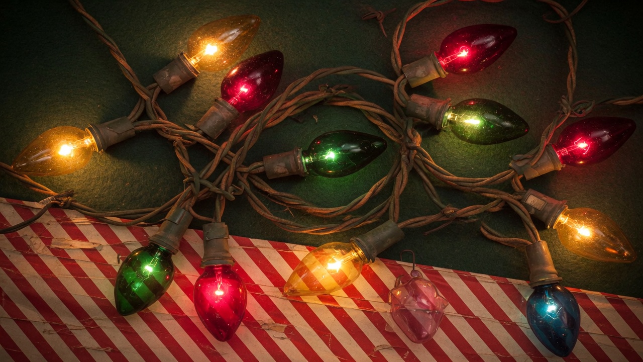
The most primitive Christmas lights used the principle of a tungsten filament heating to glow, wiring many small bulbs in parallel into a string driven directly from mains power — able to offer only a simple, single-color steady glow. For color, you dyed the glass bulb shell.
When “steady-on” no longer satisfied the market, the first generation of “moving” Christmas lights appeared: dedicated chips drove four- or eight-channel string structures to produce chase, marquee, twinkle, and fade-in/fade-out variations. The light source was still a tungsten bulb, and color was still simulated by dyeing the shell.
- Advantages: low cost and good color consistency. Even today, this class of product still holds a considerable share of the Christmas lighting market.
- Disadvantages: short lifespan, prone to secondary pollution, high power draw, and poor energy-conversion efficiency — and it is already banned in several countries.
The LED era: a revolution in four stages
When LED costs fell to a level acceptable for consumer products, three traits — energy saving, long life, and chip-native color — brought a revolutionary change to Christmas lighting. In decorative applications, going LED did not happen in one step, but passed through four clear stages.
Stage one: direct replacement
Different-colored LED bulbs were combined into a string to directly replace tungsten bulbs, achieving long life, low power, and vivid color. Representative products are single-color LED bulbs and “polarity-free lights” (using polarity reversal to drive two-color LEDs).
Stage two: built-in pattern chips
The driver chip and the LED light source were integrated into one bulb, with simple pattern variations pre-stored in the chip’s memory. After power-up, each chip automatically runs its variations per its internal program — two-color alternating flash and seven-color cycling flash are representative of this generation.
Manufacturing was simple and cost was low, but it had one inborn flaw: the oscillation frequencies of the chips drift apart over time, so the beads gradually lose sync, and pattern consistency cannot be maintained.
Stage three: master controller + pre-stored patterns
A master controller sends commands to trigger the pattern databases pre-stored in each bead’s chip, and a manually arranged sequence composes effects such as flow and marquee. The external signal solved the sync problem of frequency drift, and the master controller only needed to send simple commands, keeping cost low. But the price was equally clear:
- Each bulb had to be placed one by one in a preset order, with no interchangeability, so workers easily mis-ordered them;
- Bulbs of different orders were an enormous burden on production and warehouse management;
- The more patterns, the more chip memory they occupied, so cost stayed high, and variations were limited by masking or wire-bonding options.
Stage four: full pixel control — the bead is only a player
In the last stage the thinking flipped entirely: the bead no longer remembers any pattern; it does just one thing — receive the address code and grayscale data carried by an external signal, and when it finds its address matches, execute its own color, brightness, and timing parameters.
Every bead becomes a “player,” and what it emits is defined entirely by external data. So the same bead can support real-time (on-line) or pre-stored (off-line) signals, composing applications from points, to lines (strings), to surfaces (mesh lights, curtain lights), to 3D (light sculptures) — from then on, Christmas lights can “play content,” not merely “flash.”
External signal control: technology borrowed from the display screen
The technical origin of external signal control is the LED display screen. The master system feeds a video signal to the driver chips, controlling each LED’s brightness and grayscale, and uses a higher operating frequency with duty-cycle scanning to control many points. Representative chips are constant-current drivers such as the 8-bit 74HC595 and the 16-bit MBI5026 — but their multi-channel output pins only suit displays with dense pixel pitch that can be routed on the same PCB.
Display-screen chips cannot meet the large-span, low-density needs of advertising lights, so the “single-point (three-channel) control chip” was born and kept evolving in the direction of fewer connections:
- Five-in five-out (clock, data, latch + power): directly inheriting the display architecture, with many solder points and five required wires;
- Four-in four-out: the latch function integrated into the chip, saving one wire;
- Three-in three-out (signal + power): clock and data modulated onto the same port — this is the three-wire architecture that still dominates the light-strip market today, with representative products including the WS2811/2812 series.
The three-wire scheme transmits fast (8 MHz), a single port can drive thousands of beads, and the host software is standardized; more than a decade after its debut, it is still the market mainstream. But it has one hard-to-cure weakness: the signal is passed bead by bead, so if any one bead in the string fails, the signal is cut and every bead after it goes out of control. The break-through-resume version can tolerate only a single failure, and needs one more signal wire, so market acceptance is limited. This has kept the shift-register architecture from truly entering the high-reliability, high-end outdoor market.
The address-code era: every bead has a name
The fundamental way to solve single-point failure is to give every bead its own address. The earliest practice came from the DMX512 protocol, defined by the United States Institute for Theatre Technology on the EIA-485 interface: controlling 512 nodes at 250 Kbps with 256 grayscale levels, where addresses can be written and updated via a programming line.
DMX512 was widely accepted in stage lighting, European and American customers could write their own patterns, and — because there is an address code — a single light’s failure does not spread. But at 250 Kbps, the frame update (FPS) is not smooth under many-light applications, and the unit cost is on the high side, destining it to remain in the professional stage and engineering market.
Power-line carrier: back to two wires
Shift register needs at least three wires, and DMX512 needs five ports — but a traditional Christmas bulb has only two legs. To upgrade the hundreds of millions of existing-structure strings to pixel control, using the power line to transmit both power and data at once is the only option.
The key to power-line carrier technology is not “whether it can transmit,” but how, in the shortest time, to effectively assign and identify each bead’s positional address code — which determines whether the product can enter automated production. From early probe fuse-tuning and laser-trimmed metal fuses to the poly-fuse dual-layer address architecture that can be written in-line on the production line, address-writing speed evolved from manual bead-by-bead handling to 2,400 beads per hour completed in sync with string assembly — and only then did the full-pixel-control era of Christmas lights truly arrive.
For the complete engineering comparison of the carrier architecture with three-wire and DMX512, we wrote a deeper analysis: Shift Register, DMX512, Power-Line Carrier: A Full Breakdown of the Three Major LED Pixel-Control Technologies; for the address-code process details of carrier chips, see Core Technology.
| Generation | Light source | Control method | Fatal limitation |
|---|---|---|---|
| Rice-bulb era | Tungsten + dyed bulb shell | Direct mains / four-to-eight-channel chip | Short life, high power, banned in many countries |
| LED replacement | Single-color LED | Direct drive / polarity reversal | Only steady-on and simple two-color |
| Built-in pattern chip | Integrated LED bead | Patterns pre-stored in chip | Frequency drift, cannot sync |
| Master + pre-stored | Integrated LED bead | Command-triggered built-in patterns | Manual arranging, high memory cost |
| Full pixel control | Addressable RGB/RGBW bead | Address code + grayscale data | — (production process is the new threshold) |
FAQ
Why does one dead bulb make a whole traditional Christmas string go dark?
Traditional tungsten strings mostly use series power, so one burned-out filament breaks the entire loop; LED pixel strings that use a shift-register architecture pass the signal bead by bead, so any one chip failing interrupts the signal downstream, leaving everything past the fault point out of control. Beads with independent address codes (such as DMX512 or power-line carrier architectures) avoid a single failure spreading.
What is a pixel-controlled (fully pixel-controlled) Christmas light?
Pixel control means every LED bead in the string can be independently controlled for color and brightness. The controller sends each bead an address code and RGB grayscale data; when a bead recognizes its own address it executes the corresponding lighting parameters. This makes it possible to build flow, chase, text, patterns, and even video-grade dynamic effects.
What makes LED Christmas lights better than traditional tungsten lights?
LED Christmas lights save energy (their energy-conversion efficiency is far higher than tungsten's heat-to-light), last longer, and produce color at the chip rather than by dyeing the bulb shell, so colors are more saturated and do not fade. Because tungsten bulbs draw a lot of power, have short lifespans, and cause secondary pollution, they have been banned in several countries.
Why is it hard to upgrade traditional Christmas lights to pixel control?
A traditional Christmas bulb has only two legs (two power wires), while mainstream pixel-control technologies need extra signal lines: shift register needs three wires, DMX512 needs five ports. To achieve pixel control without changing the two-wire structure, you must use power-line carrier technology, modulating the address and data onto the power line.
Upgrading your string lights to full pixel control?
Power MOS Electronics delivers the complete stack — driver ICs, addressing equipment, controllers and apps. Tell us about your product and our engineering team will spec it with you.
Contact PowerMOS Browse products