Modulating address and grayscale data onto the power line sounds elegant, but in engineering you have to face a harsh fact: the power line was never designed as a channel for signal transmission. It attenuates, distorts, and is full of noise. Starting from the channel physics of narrowband power-line carrier, this article dissects how the symbol-decoding IC in addressable beads reliably delivers a '0' and a '1' to every bead over this hostile channel.
Modulating address and grayscale data onto the power line sounds elegant, but in engineering you have to face a harsh fact: the power line was never designed as a channel for signal transmission.
It attenuates, it distorts, it’s full of noise. Starting from the channel physics of narrowband power-line carrier, this article dissects how the symbol-decoding IC in addressable beads reliably delivers a “0” and a “1” to every bead over this hostile channel — which determines how many lights a carrier pixel-control solution can drive, how fast it runs, and how stable it is.
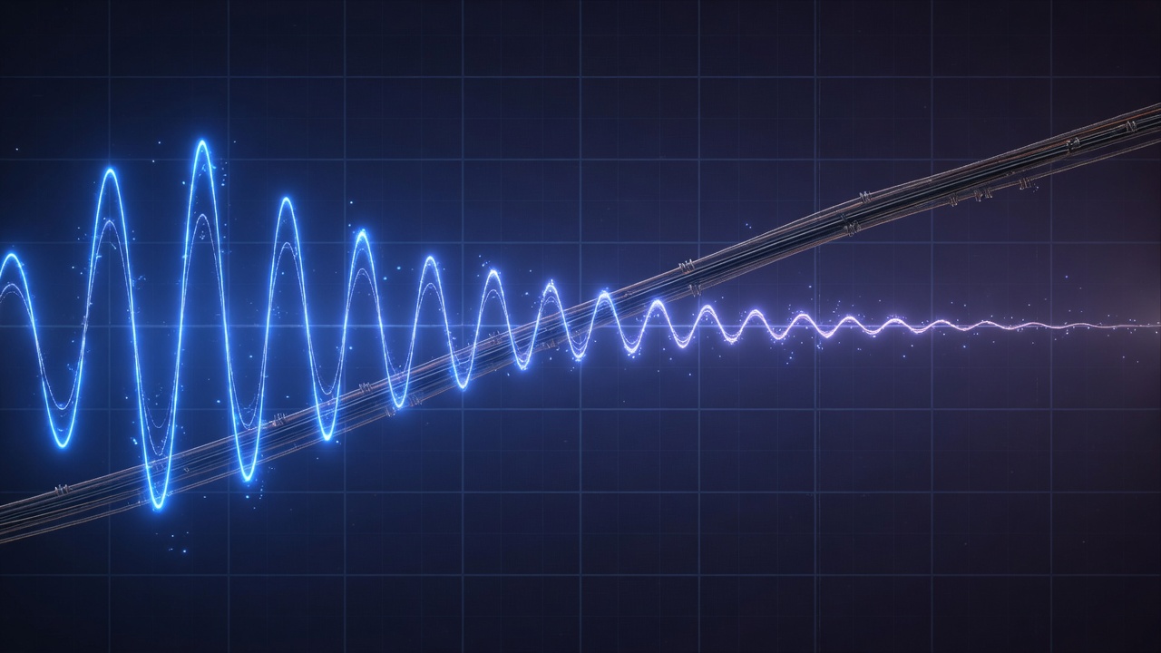
The channel’s three enemies: attenuation, distortion, noise
The technical scope of narrowband power-line carrier can be referenced against IEEE Std 1901.2-2013 — the low-frequency (below 500 kHz) narrowband power-line communication standard, which defines the physical layer for transmitting data over the power line in smart grids[1]. The PowerMOS chip’s operating frequency of about 200–330 kHz falls squarely within this low-frequency range.
The standard and related literature repeatedly point to three inherent difficulties of the narrowband power-line channel[1]:
- Attenuation — signal energy is lost to the wire’s internal resistance; the longer the string, the weaker the signal at the far end.
- Distortion — parasitic inductance and capacitance deform the edges of the square wave, making decoding difficult.
- Noise — the grid is full of surges and high-frequency noise, and in multi-wire bundles the out-of-sync signals also interfere with one another.
Together these three set the boundary of reliable transmission. The whole engineering of the decoding IC is about pushing that boundary outward on this hostile channel.
Decoding engineering: three countermeasures
A raised logic level
Once signal and power share two wires, the traditional method of distinguishing logic by 0V/5V fails — because there’s always supply voltage on the line. The carrier architecture sets a raised low level that always stays above the chip’s reset voltage, and encodes “0” and “1” above this level with PWM. The level must never drop low enough to trigger a chip reset, or the bead would lose its state.
Falling-edge decoding
The parasitic inductance of a long wire makes the rising edge and level width of a square wave unstable. PowerMOS’s countermeasure is to time the symbol from the signal’s falling edge, minimizing the impact of parasitic-inductance waveform distortion. This is especially key in the multi-wire bundles of net lights and curtain lights — where the signal-integrity challenge is most severe.
Narrow-pulse noise filtering
When several signal lines are twisted into a bundle, the out-of-sync signals interfere and produce high-frequency spikes. The chip treats narrow pulses under 1µs wide as noise and ignores them, avoiding misreads. This lets multi-wire applications like net lights and curtain lights decode reliably too.
String length vs. refresh rate: an inevitable trade-off
The limit of signal integrity ultimately shows up as two mutually constraining metrics.
String length is set by attenuation: the single-channel limit is reached when the signal has attenuated to the point where the decoding circuit can no longer reliably tell “0” from “1.” Refresh rate (FPS) is set by data volume: the time to send an entire string of address data lengthens as bead count rises, so single-channel FPS falls accordingly.
For example, estimating at a 3µs symbol rate, a single string of 200 beads runs at about 16 FPS. This is a trade-off — large-scale applications can’t force it through a single channel, but instead spread the load across multiple channels, meeting both bead count and smoothness at once.
From signal engineering to selection
These signal-integrity techniques ultimately decide how many lights a solution can drive and in what voltage environment it stays stable. PowerMOS builds surge protection into the fuse zone, and, paired with the decoding engineering above, improves the stability and string length of high-voltage AC110/220V applications. See core technology for details; for each model’s symbol rate and detection-voltage parameters, see the product center.
Further reading: for display quality on top of the signal, see Grayscale, Color, and Flicker-Free Dimming Engineering for Addressable LEDs; for the standards context, see The Two-Wire Debate in Addressable Lighting.
Reference Standards and Literature
- IEEE Std 1901.2-2013, IEEE Standard for Low-Frequency (less than 500 kHz) Narrowband Power Line Communications for Smart Grid Applications. IEEE Standards Association.
- IEEE Std 1901-2020, IEEE Standard for Broadband over Power Line Networks: Medium Access Control and Physical Layer Specifications. IEEE Standards Association.
- IEC 61000-4-5, Electromagnetic compatibility (EMC) — Surge immunity test. International Electrotechnical Commission.
This article is an educational overview of signal engineering. The names and numbers of the standards cited can be verified in the official catalogs of the IEEE Standards Association and the IEC. PowerMOS addressable-control ICs use a proprietary narrowband carrier protocol optimized for LED pixel control, not an implementation of the standards above.
FAQ
Why is the power line called a 'hostile' signal channel?
As narrowband power-line carrier literature such as IEEE 1901.2 describes, the power line is designed to deliver power, not to transmit signals. A signal traveling on it meets three inherent difficulties: attenuation from the wire's internal resistance, waveform distortion from parasitic inductance and capacitance, and the grid's own surges and high-frequency noise. Together these limit the distance and rate of reliable transmission.
How does power-line carrier pixel control distinguish signal from power on the shared line?
Once signal and power share two wires, the traditional method of distinguishing logic by 0V/5V no longer works. The carrier architecture sets a 'raised low level' that always stays above the chip's reset voltage, and encodes '0' and '1' above this level with pulse-width modulation (PWM), which the bead's internal demodulation circuit recovers. The level must never drop low enough to trigger a chip reset.
Why use 'falling-edge decoding' rather than level-width decoding?
The parasitic inductance of a long wire deforms the edges of a square wave and makes the rising edge and level width unstable. Timing the symbol from the signal's falling edge minimizes the impact of the parasitic-inductance waveform distortion and makes decoding more stable — especially in the multi-wire bundles of net lights and curtain lights, where this is key to interference resistance.
Why do string length and refresh rate constrain each other?
Signal attenuation limits how many beads a single channel can reliably connect; and an addressable bead's frame refresh rate (FPS) depends on the time it takes to send an entire string of address data — the more beads, the longer each frame's data and the lower the single-channel FPS. So string length and refresh rate are a trade-off. Large-scale applications spread the load across multiple channels, meeting both bead count and smoothness at once.
Which PowerMOS technologies do these signal-integrity techniques correspond to?
In its decoding logic, the PowerMOS chip combines techniques such as a raised low level, falling-edge decoding, and narrow-pulse (under 1µs) noise filtering, with built-in surge protection in the fuse zone, to extend the number of beads a single channel can reliably connect and to improve stability in high-voltage applications. Its operating frequency is about 200–330 kHz, within the low-frequency range of narrowband power-line carrier. See the core technology page for details.
Upgrading your string lights to full pixel control?
Power MOS Electronics delivers the complete stack — driver ICs, addressing equipment, controllers and apps. Tell us about your product and our engineering team will spec it with you.
Contact PowerMOS Browse products